THE DETAILS:
It was determined that carbon fiber filled polycarbonate would provide sufficient strength to withstand the significant forces used in the stretch form process, however unlike traditional lubrication methods, Techmer PM blended a new polycarbonate formulation that contained an internal lubricant in addition to the carbon fiber, eliminating the need for any additional lubrication.
THE PROCESS:
The tool was printed on Thermwood’s LSAM 1020 dual gantry print and trim system. While this machine is equipped with Vertical Layer Printing and could have printed the tool in one piece, because it requires that you to wait for each printed layer to cool enough before adding the next layer, it would have required 58 hours of continuous print time to produce a one-piece tool. Instead they decided to print the part in four sections, two at a time for a total print time of 29 hour and 20 minutes, cutting the print time in half. Printing required 3,613 pounds of material.
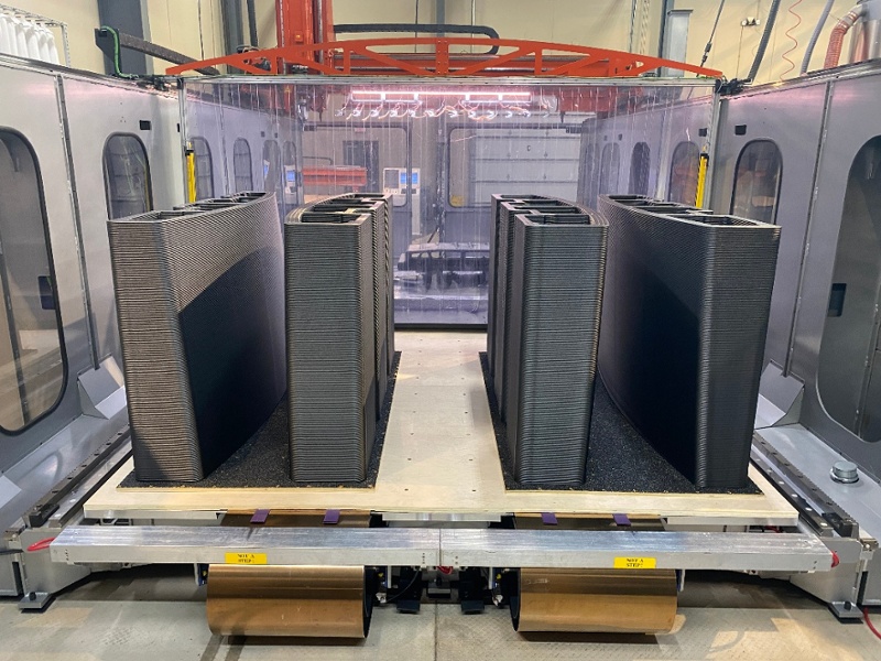
The Four Parts Printed
The four parts then needed to be machined and assembled.
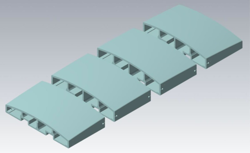
Layout of the Assembly
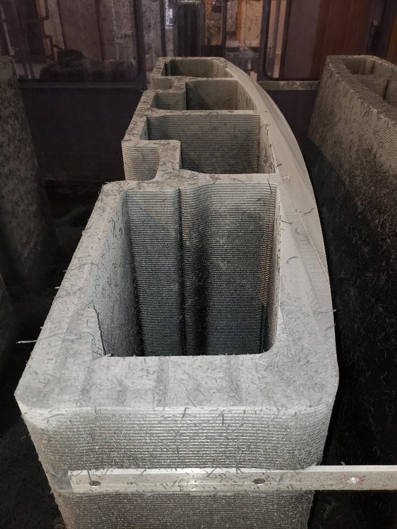
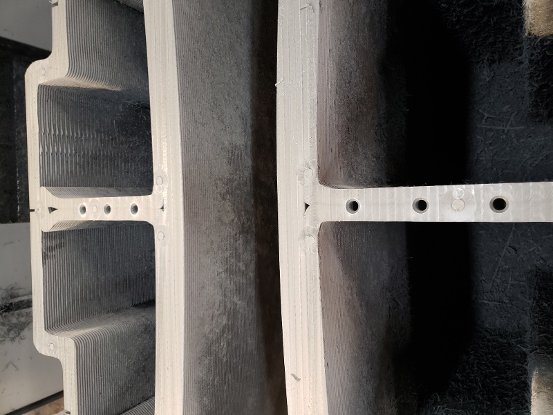
All surfaces of the parts except for the front working surface were then machined in place.
Initial machining. The holes in the center of each side are for center-of-gravity brackets used for part handling during assembly.
The mating faces were then machined flat except for slightly raised bosses which insured proper gapping for the adhesive. Adhesive is only one part of a multi part approach used to permanently and securely attach the parts to each other. These are all highly accurate, precision surfaces.
Flat Face has raised bosses to provide proper adhesive gap
PUTTING IT ALL TOGETHER:
Draw bolt holes and slots were machined into the back of the tool which allow the parts to be bolted together in addition to the adhesive.
Machined area for draw bolts
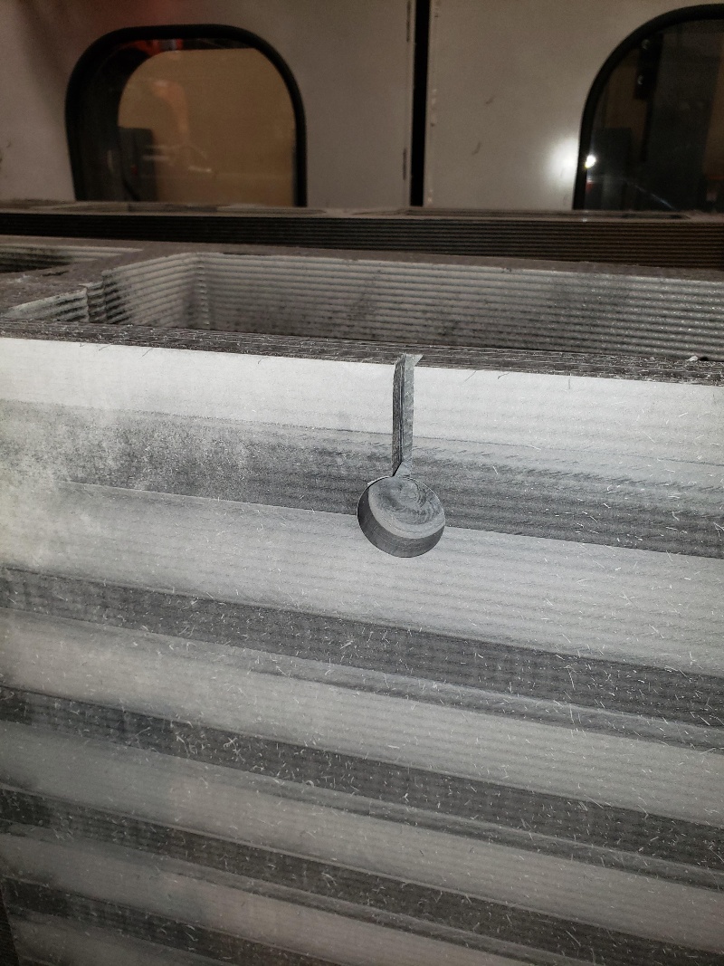
In addition to adhesive and draw bolts, alignment holes and countersink holes were machined into the center sections of the tool.
The 6-inch long alignment pins for these holes are machined with adhesive channels providing not only alignment between parts but also another level of permanent attachment.
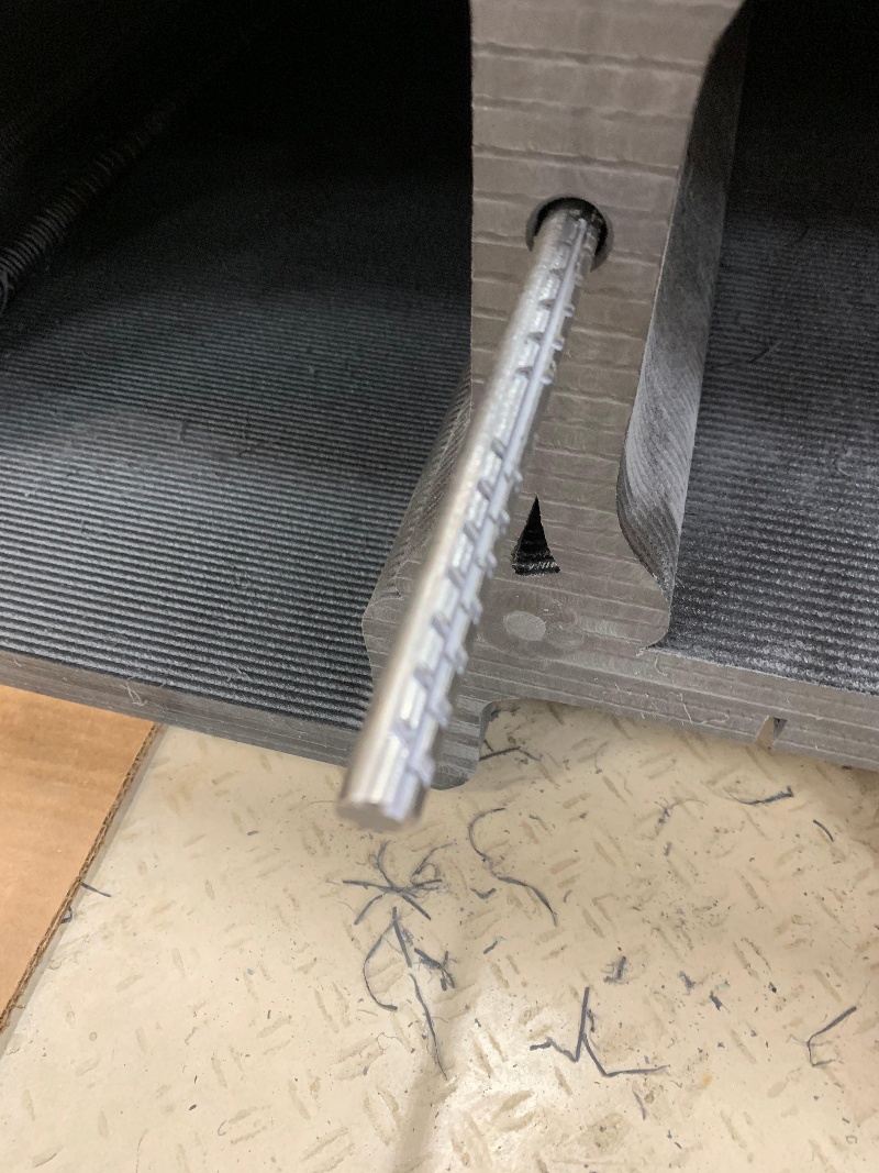
Heavy duty alignment pins offer another attachment layer
The next level of attachment uses brackets positioned inside the structure near the front surface, which are attached to each other using tensioned aircraft steel cables, securely holding the front surface of the four parts together.
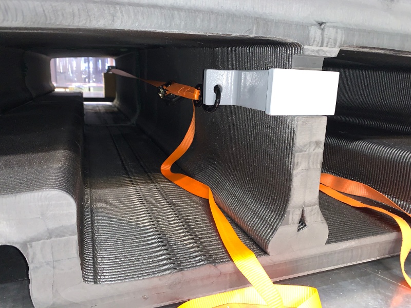
Brackets with temporary straps which were replaced by tensioned steel cables
The parts were then final assembled using another unique approach. Each part is relatively heavy and because of relatively short open time for the adhesive, there is a limited amount of time available during assembly to apply the adhesive and mate the parts securely together. The parts need to be pushed together while aligned, literally within a few thousandths of an inch and need to be mated absolutely even and square. This turned out to be fairly easy using the Vertical Layer Print table mechanism installed on the LSAM machine.
The parts were carefully hand fitted together. Then, one part was attached to the machine table and the other to the mechanism that moves the vertical table. The vertical table drive then moved the parts apart about 20 inches, adhesive was applied and the vertical table mechanism pushed the parts back together again, square and perfectly aligned.
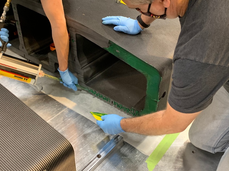
Adhesive being applied to separated pieces
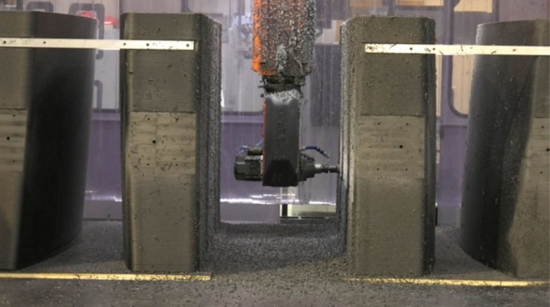
Draw bolts and cables were permanently attached and after the adhesive fully cured, the completed tool front surface was machined to final dimensions using the LSAM trim head. When Spirit AeroSystems measured the final working surface it was within +/- 0.005”, well within their requirements. Total of all machining including the final working surface was 118 hours and 58 minutes.
THE RESULTS:

Front surface measured to within +/- 0.005"
Spirit AeroSystems then stretched 10 skin panels of 0.050” thick 2024 T3 aluminum to 5% elongation. The press controller showed that each jaw gripping the aluminum sheet had ~100 tons of load on it, so ~200 tons in total. Everything was kept under the same conditions as if running a production part and although the printed tool was considerably lighter in weight than their traditional tools, it appeared to perform in a similar manner.
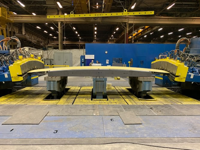
Skin panel being stretched
THE BOTTOM LINE:
This is a first step. There are additional tests to be performed and more data to be collected, but it does appear that large 3D printed composite stretch form tools can be produced using currently available material and current equipment, saving considerable time and money and opening yet another application for this exciting new technology.
ABOUT SPIRIT AEROSYSTEMS:
Spirit AeroSystems is one of the world's largest manufacturers of aerostructures for commercial airplanes, defense platforms, and business/regional jets. Also, Spirit serves the aftermarket for commercial and business regional jets.
ABOUT THERMWOOD:
Thermwood is a US based, multinational, diversified machinery manufacturer that has become the technology lead in large scale additive manufacturing of thermoplastic composite molds, tooling, patterns and parts with its line of LSAM (Large Scale Additive Manufacturing) systems that both 3D print and trim on the same machine.